Technical Downloads & Wiring Diagrams
Access official Xhorse software updates, PC suites, device drivers, mobile apps, instruction manuals, and bench wiring schematics.
Xhorse Official Mobile App
Sync key cutting databases, calculate online tokens, update Key Tool Max Pro, and manage remote functions.
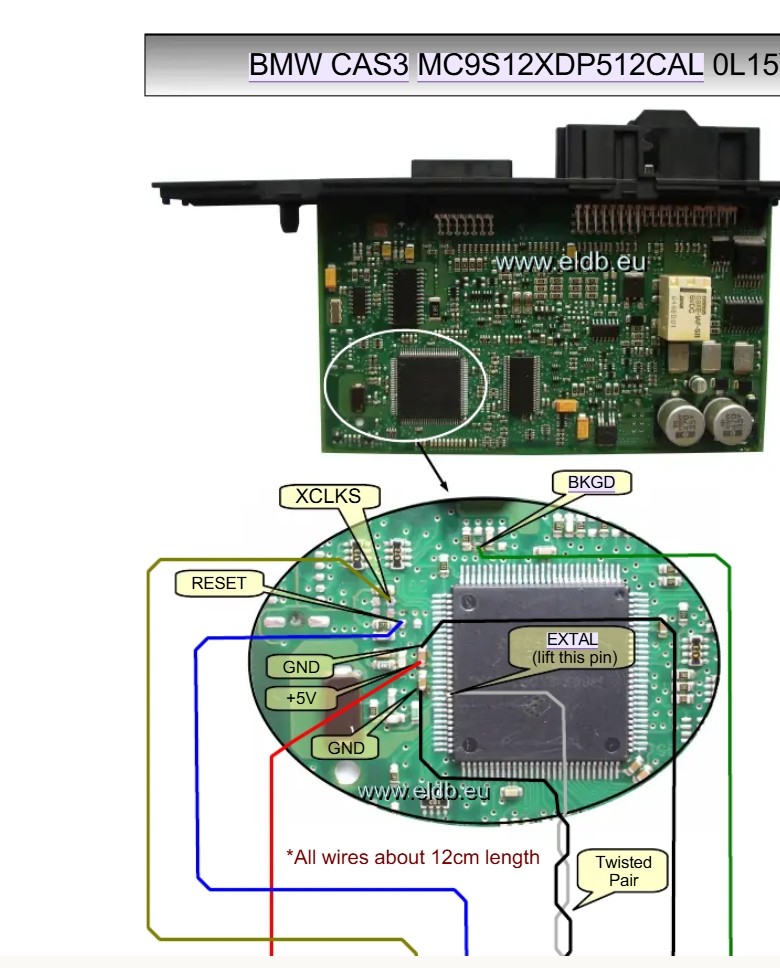
BMW CAS3 / CAS4 Bench Pinout Guide
VVDI Prog solder points & adapter wiring diagram
BMW FEM / BDC Bench Connection Diagram
Key Tool Plus & VVDI Prog wiring harness pinouts
VAG MED17 / EDC17 Boot Pinout Schematics
ECU solder points for Bench ISN & EEPROM reading
Mercedes EIS / EZS Bench Wiring Index
W204, W207, W212, W166 password read wiring
MCU & EEPROM Solder Adapter Guide
Solder diagrams for 8-pin EEPROM & Motorola MCUs
Toyota / Lexus All Keys Lost Cable Diagram
8A AKL adapter & smart box connection points
Xhorse Update Kit
Official PC software utility for upgrading device firmware
VCP Driver Package
Virtual COM Port drivers for USB device connectivity
VVDI Prog PC Desktop Suite
Latest software suite & chip database for VVDI Prog
VVDI2 Desktop Suite
Software suite for VAG, BMW, and Porsche key functions
VVDI MB Tool PC Software
Desktop software suite for Mercedes key programming
Multi-Prog Desktop Suite
Full desktop software & ECU/MCU database package
Dolphin XP-005L User Manual
Setup, clamp calibration, and operation guide
Dolphin XP-007 Manual
Manual key cutting machine operation & cutter setup
Condor XC-Mini Plus II Manual
Complete user manual & cutter replacement guide
Condor XC-002 Pro Manual
Manual high-security key cutting calibration guide
Key Tool Max Pro Manual
OBD programming, CAN FD, & transponder cloning guide
VVDI Key Tool Plus Manual
Full system diagnostic & key programming manual
VVDI Prog Programmer Manual
EEPROM, MCU, & ECU bench reading manual
Multi-Prog User Manual
Batch programming, MCU soldering, & ECU clone guide
BMW CAS3 Microcontroller Pinout Reference

| Signal Line | Wire Color Code | Connection Point / Function |
|---|---|---|
| +5V | Red | Main VCC Power Supply connection point. |
| GND | Black / Blue | Ground reference connection points. |
| RESET | Blue | Microcontroller Reset line for BDM / programmer control. |
| BKGD | Green | Background Debug Mode single-wire data interface. |
| XCLKS | Yellow / Off-white | External Clock Select line signal. |
| EXTAL | Single Wire (Pin Lift) | External Oscillator input. Pin must be lifted off the PCB pad during reading. |
- Wire Length Limit: Keep all signal interconnect wires strictly under 12 cm (~4.7 inches) to avoid signal reflection and timing errors.
- Twisted Pair: Twist data signal wires together as indicated to minimize electromagnetic interference (EMI) during EEPROM / FLASH operations.
- Pin Lifting: The
EXTALpin must be desoldered and lifted off the circuit board pad to bypass on-board clock interference with external programmers (e.g., XPROG, VVDI Prog).